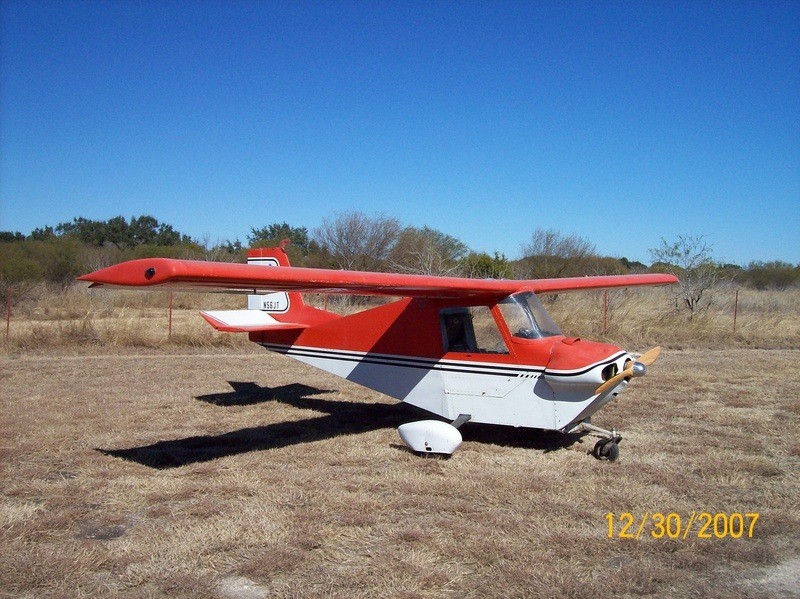
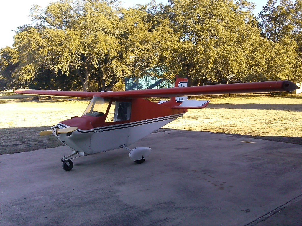
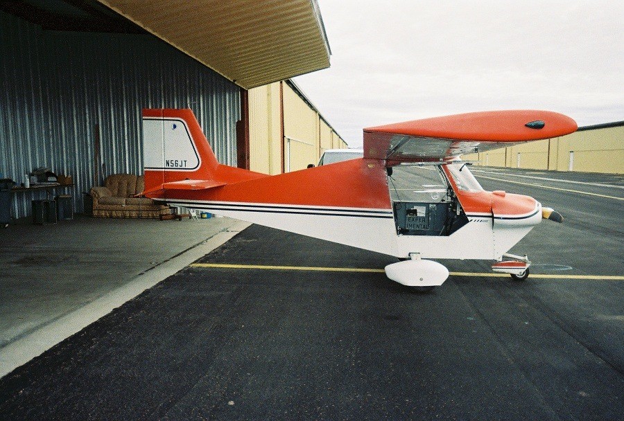
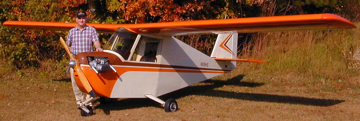
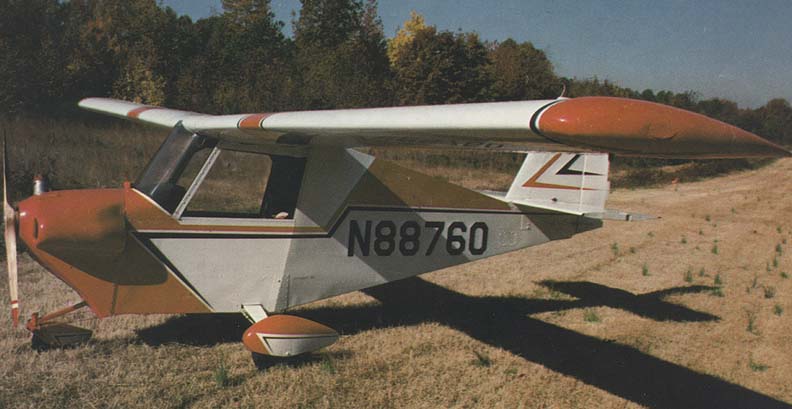


The Aerosport Quail is an ultralight aircraft that was designed for home building by Harris Woods.
First offered for sale in 1971, by the end of the decade, 375 sets of plans had been sold, with around 26 aircraft under construction and 10 flying.
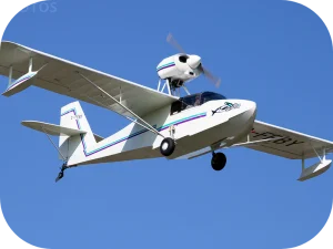
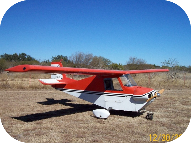
The Quail is an all-metal cantilever high-wing monoplane with an enclosed cabin and tricycle undercarriage. The aircraft uses simple flat-sided construction with pop-rivet assembly. The wing design is unmodified from the Aerosport Rail homebuilt. The prototype was powered with a Rockwell L680R engine.
General characteristics:
Crew: 1
Wingspan: 24 ft (7.3 m)
Wing area: 84 sq ft (7.8 m2)
Empty weight: 435 lb (197 kg)
Gross weight: 750 lb (340 kg)
Fuel capacity: 8
Powerplant: 1 × Volkswagen Horizontally opposed piston, 50 hp (37 kW)
Propellers: 2-bladed
Performance:
Maximum speed: 109 kn; 201 km/h (125 mph)
Cruise speed: 104 kn; 193 km/h (120 mph)
Stall speed: 39 kn; 72 km/h (45 mph)
Range: 196 nmi; 362 km (225 mi)
Service ceiling: 12,000 ft (3,700 m)
Rate of climb: 820 ft/min (4.2 m/s)
Wing loading: 8.92 lb/sq ft (43.6 kg/m2)
Aerosport Quail Builder’s Manual Introduction
Congratulations on your choice of the Aerosport Quail for an amateur-built project. Aerosport has conscientiously attempted to eliminate as many difficulties as possible in our efforts to produce the best possible product. The Construction Drawings are the most thoroughly detailed set of plans we have seen, which will be of great advantage to you. Every nut, bolt, and piece of hardware is indicated on the drawings. Every piece of metal is specified by proper nomenclature.
We recommend that you thoroughly study these drawings for many hours until you understand how each piece fits into the scheme of things. You should rapidly notice that each sheet is limited to one or two major parts of the airplane. For example, the Wing Drawing, Tail Surfaces Drawing and Fuselage Drawings. There are seven sheets of Drawings. The apparent complexity you see at first glance is very deceptive. Once you study the drawings and compare them to the photographs in this manual, you will begin to realize how simple the aircraft really is. In many ways, we believe the Quail to be the most simple-to-build airplane in he world.
You are about to embark on an extended journey that can be as simple or difficult as you want to make it. You can build this airplane in three or four months, or in two years. Our demonstration airplane was assembled in two months and has received many compliments. The point is this: If you work smoothly and positively and “get with it,” you can have a fine airplane very shortly. Or you can become a “piddler” and work minor details into weeks of effort. For example, you can cut a piece of aluminum angle to size, and rapidly smooth the cut surface to a safe, minimal fatigue area. Or you can cut the piece 3/32” too long, and spend an hour filing off aluminum to get the proper dimension.
We have responsibly developed a fine product, which can be rapidly built and flown. We have drawn our plans so that you could build the airplane without purchasing anything else from us except the engine and prop. But we do recommend that you purchase machinings and spars and complex items from Aerosport. The time, money and heartaches this will save you are substantial. For best, most efficient results, we continue to recommend that you buy the Complete Quail Package. With the Complete Package, you can be assured that only aircraft standard hardware and materials specified by the designed are furnished. The time and frustration you avoid will offset any minimal cost savings.
So go to it. The airplane is a good one and, at the end of your pleasurable journey, is the added regard of some of the most thrilling, economical fun-flying possible. Try it and see.
Where to Begin
Before you hurriedly start cutting out pieces, Aerosport feels that we should introduce you to three phases of Quail construction. First, the concept of aircraft standards. Second, the need for certain tools. And third, basic techniques of aircraft building.
Aircraft Standards? What Are They?
It is very important that you learn to appreciate the need for complying with the quality standards designed into the Quail, as well as those for any other airplane. Aircraft performance, especially in a very light airplane like the Quail, is very dependent upon keeping the aircraft weight to a minimum. Furthermore, the airplane is designed with materials that provide optimum strength for a given weight. Let me explain. Suppose you use soft low-grade aluminum alloy to build your spars. Indeed they would be easier to form, as soft alloy is much more malleable than the aircraft alloys. Yet the strength factor of 5.7 g’s built into the airplane could be reduced to 2 g’s or less. In other words, the aircraft wings could literally collapse in a 45-degree banking turn. For this reason, you must use the alloys Aerosport recommends. It is very important to your safety. Another example: Using electrical conduit for pushrods. The column strength of conduit is a mere fraction of 6061-alloy tubing. Any such substitutions are very risky indeed. Aircraft hardware? Shear strength of aircraft bolts is several times that of common automotive and discount store hardware. Do you want to risk your life with such obvious foolishness as substitution of parts? Please stick with the design specifications.
Generally speaking, if you were to substitute materials of ½ the strength specified, you would need twice the material to obtain equivalent strength. The Quail, built of such materials, would be so heavy it wouldn’t fly. Your project would make a particularly expensive piece of lawn furniture, wouldn’t it?
Most simply, designers use the lightest, strongest materials available to keep aircraft weight to a minimum, so you can have fine performance. Don’t set out to defeat them!
Tools you will need.
Aerosport furnishes a small sheet-metal brake, a pop-riveter, and some special drill bits with the Complete Quail Package. Other tools necessary include common hand tools, vise, aircraft shears, Clecos, C-clamps, and a large, flat table. We emphasize that you first construct a 3 ½’ x 12’ table of absolutely flat surface. Our table cost $40 for a super adequate job. This seems like a lot, but it is serving well as an additional workbench in our shop, and would be as nice for yours too. If it is perfectly flat, you can build your wings and tail surfaces with a minimum of jigs.
You must have the following tools for precision measurement: A machinist’s protractor, try-square, steel rule and steel tape. Recommended power tools include a drill press, hand drills and a band saw.
A band saw is the handiest tool we know of for cutting out aluminum plate and angle 1/8” thick and over. Get a special metal-cutting blade for yours. You will save countless hours with one. A belt sander speeds the finish shaping of many pieces. Also, the old-style automotive body file (for working lead) is a handy tool for finish shaping and smoothing aluminum.
Aircraft Construction Techniques
Many homebuilt airplanes are made of wood and fabric and steel tubing. While these methods have many virtues, it is wise to notice that most aircraft manufacturers have turned to all-aluminum construction. Why? Not necessarily because all-aluminum airplanes are better, but because the skill level required of factory workers is much lower. This truism works in your favor on the Aerosport Quail and several other homebuilt designs. Most of us, whether we admit it or not, have no capability to weld up a fuselage out of aircraft tubing. But anyone can be trained to drill holes in tubing and skin, and bolt and rivet components together safely. This is one of the major reasons we developed the Quail the way we have: so you could do it yourself!
Well, what techniques do you need to know? Many, of course. Let us explain the how’s here, and then proceed to individual components construction later.
Reading the Plans
Each dimension is accurately listed on the plans. Each part is numbered (such as F-11 Fuselage Side Skin) and its proper size and material specification noted. Each piece of hardware (nut and bolt) is indicated, with its proper specification listed. Most items are full scale, unless otherwise noted. Study the plans, the photos in this manual, and every step suggested in the write-up on building each component, such as the wing or rudder, until you know how to make it.
There are three methods of transferring the shape of each piece from the plans to the metal material. First: by placing carbon paper under the plans and on the metal, and tracing along the plans (use a straight-edge for best accuracy). Make certain nothing moves, and locate each hole to be drilled by tapping a punch through the plans to the metal at each point. Remove the plans and carbon, and your shape will be on the metal! The second method is to spray a light coat of machinist’s dye on the metal, and then transfer all the dimensions to the metal with a scribe by measurement. Be very careful to use a square, working from one side only to keep things true. Punch at the appropriate spots for holes. Use each method, choosing your own preference in each case, depending upon the difficulty of duplicating the shape. The third method is to cut out the drawing, lightly cement it to the metal, and then cut it out. Where holes are to be drilled, be certain to locate them accurately and center punch them first. It is often sensible to drill the holes before cutting the part out so you can more easily clamp the material in a vise. Follow the instructions for drilling below.
Warning
The sensible approach to building each component is to first make all the pieces, sub-assemble them, (such as attaching plates and angles to the spars), assemble each component, and then move on to the next one. But you must use care when making each piece. For example, many pieces should be match-drilled. Drill one piece, clamp it in place, and then drill through it, accurately transferring the hole, so you don’t mis-locate a hole. Don’t drill every hole in sight, then discover that the pieces don’t go together. It is true that Henry Ford discovered mass production, which means all pieces go together automatically, but each item he built was jig-drilled, which is a glorified way of match drilling. Hand building an airplane reverts to the old-world craftsman’s techniques of “drill, fit, test, check and drill the other piece!” You use it too, for best fits!
Drilling and Boring
Where 1/8” rivets are to be used, drill with a #30 bit, which allows you to rivet without stretching the metal. All other holes using special bits are noted. In critical attachment points, please be very careful to match-drill (drill pieces while clamped together in position). Be certain to use a center punch to accurately locate all holes: for example, lay out your rivet holes along the spars, and use a punch at each rivet. This helps prevent a wandering drill bit. Wherever possible, use a drill press to assure perpendicular holes. Use a drill press vise to hold pieces in place. When deep-boring (1/2” or greater thickness), be certain to use an aluminum boring fluid, and slowly cut in, remove the bit from the hole, and cut again, so you remove the chips rapidly. If the material gets hot to the touch, you are trying to cut too fast. Large holes may be bored with a fly-cutter, if it is a good one. Be careful, though.
Since the strength of the airplane is largely dependent upon the shear strength of the bolts and their respective holes, a good fit is very important. Avoid sloppy holes and elongating holes to make a fit. A bolt doesn’t work by clamping down, as many seem to believe. Do not drill extra holes in the tops (caps) of spars, or through the wing attachment plates, or the landing gear, its mount brackets, or the engine mount tubes and brackets. These are all the critical strength areas of each component. To drill through them is to weaken them too much.
Bending and Forming
Aircraft aluminum and steel are fairly brittle alloys. In order to bend them and retain their strength, it is necessary to bend them around a fairly large radius. If you use a smaller radius than recommended on our plans, you will most likely break the metal at the bend. If the metal doesn’t break, it will almost certainly have hidden damage that could let you down. The Quail was designed to eliminate as many bends as possible, relying on extruded angle and other methods where possible. Such pieces as rib stiffener angles and other light gauge pieces may be formed on a small sheet metal brake such as the one provided in our Complete Quail Package. Be certain to grind a 1/8” radius on its sharp edge, or it will break the metal rather than bend it. There is a tendency in the marketing of some airplane plans to suggest that you can form your wing spars by bending the metal over a piece of wood. We have found that this is almost impossible and the only way to make spars properly is with a huge hydraulic press. If you desire, you may buy spars separately from us, which are made by an aircraft factory to aircraft assembly of your airplane tremendously by minimizing alignment problems. Small pieces of heavy gauge metal may be bent by making wooden blocks with a proper radius and then clamping them in your vise. When you bend your ribs over rib-blocks, remember to use a soft hammer and tap the tabs down so that you get a perfect shape.
Riveting
The predominant portion of your riveting job is done by use of “Pop” rivets. We have found the “Flush Break” USM rivet to have satisfactory strength in both shear and tension, but you must observe appropriate techniques.
First, each hole should be de-burred, where possible. Do not enlarge the holes, however. Second, all chips must be removed, so the two pieces of metal will be attached together. For example, you should place a control surface skin in position, drill all the holes, remove the skin and blow away the chips. Be certain to retain the skin in one place by use of Cleco fasteners while drilling. A good practice to follow is to drill each end of a control surface rib, insert a Cleco, and then complete the drilling of each rib. The recommended technique for attachment and drilling of wing skins is covered elsewhere. Do not enlarge the holes you drill, as the resulting loose fit of a rivet permits it to work in the metal and become useless structurally. After cleaning and preparing each skin, as suggested, you can begin “Pop” riveting. Be sure to use the appropriate length rivet, as recommended on the plans. Insert a rivet in the gun, and work it into a rivet hold. Press down on the skin to assure contact with the rib below, and squeeze the rivet until it “pops”. Retain alignment with Cleco fasteners as you proceed.
How about regular rivets? Well, they are used in assembly of the spars, and recommended in the forward area of the fuselage. Careful use of a hammer on the stem end with the head against a steel block is a good way of riveting. Practice this technique on scrap first, however. If you have access to a rivet gun, and the skill, by all means, use it. The question is asked often regarding use of regular rivets on the airframe. It is not necessary, of course, but conventional rivets do have somewhat greater shear strength and less drag. If you desire to use them, the top surface of the wings would be the place to start. It would be fairly impossible to fully close up the wings with them though, unless you cut an inspection panel in each rib bay for insertion of a bucking bar. This would be quite impractical, as you can imagine. Used as recommended, the “Pop” rivet is entirely satisfactory. Do be certain that they are “pulling up” when you rivet blind. Don’t push the rib tabs down with the rivet and miss them entirely. Usually, you can see a slight dimple in the outer skin if they are pulling properly. If the rivets are inserted loosely, oil could cause them to work and enlarge the holes. Keep an eye on them during your flight time.
Bolting
It is appropriate to turn the nut, rather than the bolt, to avoid enlarging the bolt hole. Always use a bolt that, when the nut is tight, leaves two or more threads exposed.
Make certain that the bolt shank goes through the material, but not so far that the nut tightens on the shank rather than compressing on the material. If there is any doubt, use a washer. Aircraft hardware is generally designed so that, if over-tightened, the bolt will break rather than the nut shear out. This is a safeguard, but don’t abuse it. You should get a “touch” for tightening aircraft hardware. Once the nut is clamping on the material firmly, it starts to stretch the bolt. This is the “plastic” region of the bolt. In the plastic region, the bolt is operating as designed. You must learn to recognize this region of tightness, and tighten the bolt until it is in the plastic region. Don’t over-tighten far into that region, as it is pointless. It is also true that the bolt will stretch overnight and relax somewhat, so don’t under-tighten either!
Especially in critical areas, it is wise to toss away elastic nuts, if you remove them, as they loose their self-locking capability when removed and retightened.
Electrical Wiring and Safety-Wiring
When you reach this stage, be absolutely certain that the electrical wiring is adequately protected from chaffing. All engine wires should be bundled and tied against each other so as not to vibrate and fatigue break at their connection points.
All fuel lines should be protected from abrasion by use of rubber grommets and clamps. All engine bolts and control cables should be safety-wired. When safety-wiring bolts, be certain that they are wired so that, if one tends to loosen, it will be pulling against another. Ask an aircraft mechanic “how-to” on this, if you don’t know how. Be certain that each component is attached so it cannot work loose through vibration. Pin each control pushrod at one end, so it cannot rotate loose. Follow all practices shown on the plans.
Construction
A good place to start is with the tail surfaces. By comparing the plans and the photographs, they should be self-explanatory. First, make all the pieces, and use zinc-chromate (available in spray cans from any aircraft parts distributor) on all steel parts.
Elevator
Assemble the elevator first by attaching the E-1 ribs to the spar E-3, and then bending the trailing edge and fitting each E-2 skin. Cleco it in place during this operation, and ascertain that each rib is perpendicular and at right angles to the spar, so everything is square. Drill one side, remove, de-burr and clean, and then rivet in place. Keep chips from under the ribs. Do the same with the other side. Remember to leave un-riveted areas where the piano hinges attach. Install E-4 spar torque channel. Install the E-5 cranks as indicated on the plans, using E-6 clips, and being certain that the correct gap between the cranks is maintained.
Horizontal Stabilizer
Assemble all the HS-2 ribs to the two horizontal stabilizer spars (HS-6), keeping everything square. Attach and locate HS-7 reinforcing angles by riveting in place through the HS-6 spar webs. Attach the HS-8 spacer block where indicated, being careful to assure that it will remain located as you skin the surface. You should drill the .248” holes in the spar before skinning. A dowel could be run through these holes and the HS-8 block to hold it in place. The HS-9 block can be installed after the skinning operation. Wrap the leading edge skin around a bar to shape the radius properly. Rivet the top of the HS-3 skin in place, and drill the .248” holes for HS-8 and HS-9 from the bottom. Then rivet the bottom of the skin in place, as done on the elevator. Remember to leave un-riveted areas for the piano hinges. HS-3 is pre-shaped in the Quail package. The bottom .248” holes can be drilled at installation, or at this time.
Vertical Fin
Make V-1, V-2, V-3, V-4 ribs and V-6, V-7, V-10 nose ribs for the vertical fin and install on V-8 and V-9 spars. Make certain the V-1 through V-4 ribs are perpendicular to spar V-9, by using your try-square.
Use AD42 AFB rivets to attach the ribs. Attach clips to ribs with AD41 AFB rivets. Make skin V-6 by carefully laying it out on .016 sheet, being careful to allow enough material for leading edge wrap-around. You may choose to trim after trial fitting this piece. The V-6 skin may be lightly creased at the V-8 spar for a neater appearing job. Rivet in place with AD41 and AD42 AFB rivets, as specified on the plans.
Rudder
Building the rudder is similar to building the other control surfaces. Install the five R-4 ribs on the rudder spar R-2 with AD42 AFB rivets. Install R-6 rib in the same manner. Make the R-3 rudder skins to the dimensions on the drawing, being careful not to over-bend the flanges. Install the skins using AD41 AFB and AD42 AFB rivets, as noted on the drawings (use 1 1/2’” spacing on the ribs). Do not rivet the skin to the bottom R-4 rib until ready to install R-6 rudder horns. Use AD52 AFB rivets when putting the rudder horns on the rudder assembly. Rivet the trailing edges together with AD41 AFB rivets, spaced every 2 inches. On the leading edge flanges, Install MS 20257-P1 hinge (R-1) with 2” rivet spacing as shown on the top view of Rudder Assembly. This completes the rudder. At this point, you have a good knowledge of the techniques used to complete the airplane.
Ailerons
Cut the aileron skins from the upper and lower 30” wide .020 x 2024-T3 W-31 and W-32 skins. Dimensions are found on the Aileron Rib drawing. Be careful to remember that the top and bottom skins for the wings are now different, when you start to assemble the wings. Make W-19R and W-19L clips and install them with AD42 AFB rivets on the spars W-18L and W-18R, which are mirror images. (See the detail to the right of Aileron Spar on the wing drawing). Install the Morse Spherco FRE-4 rod ends, locating the center precisely 11/16” from the spar web. This is a critical dimension. Tighten carefully, as this will be hard to get at with the skins on!
Install the W-7L and W-7R ribs as shown, with AD42 AFB rivets. Install the skins as before, leaving room for the piano hinges, and being certain that the ribs are perpendicular to the spar. Remember, one left, and one right aileron.
Wings
Here is where the large, perfectly flat table is so important. We recommend a 3 ½’ x 12’ table. We also recommend that you purchase your spars and spar nesting angles from Aerosport. They are made for us by an aircraft factory, to aircraft tolerances and standards. If you do not, remember that this is a cantilever wing. All loads must be carried by the spars! Make certain the proper radius is used.
Make the W-11 and W-12 attachment plates (2 each). Match drill one pair at a time using a .312” and 3/16” drill as noted. Drill only the top .500” hole, after assembly of the spars. Then when the wings are installed on the plane, put a bolt through the top spar attachment, and juggle the angle to obtain proper dihedral and then drill the bottom .500” hole.
Lay the W-9L, W-9R and W-10L nesting angles in the W-8L and W-8R spars and drill with a #22 (.157”) drill at the spacing shown. Rivet with conventional AD5 aircraft rivets (you may use a hammer or rivet gun to upset them). Rivet only in the web area, not the cap. Cut out the holes for the pushrods at this time, and locate and drill the six holes for attachment of W-13L and W-13R drive crank supports. Do not install until later. Install the W-11 and W-12 attachment plates as per drawings, leave wing attachment hole un-drilled until wing installation.
Make the ribs W-2 and W-3 by making bending blocks out of plywood, to the shape shown in the rib section, with an 1/8” radius, and about a 15 degree undercut to permit over-bending of the flanges. (You will need a right and a left hand set of blocks. Use jig holes in rib blanks and in jig pins blocks for proper alignment). Cut out rib blanks to the shape shown, including the flanges. Then stack-drill the blanks with a #30 drill at points indicated, and drill ¼” jig holes.
Stack drill 2 ½” holes in fourteen nose rib blanks with a fly-cutter. Be certain to clamp blanks to drill press. Bend rib blanks on rib bending blocks, and use plastic hammer to tap down the tabs so that they are properly formed. Install ½” x ½”clips as shown on the drawings. (Note: Ribs are preformed in our Quail wing package. It is not necessary to drill the #30 holes in their flanges prior to assembly. This will be explained later in the manual).
Make the W-15R and W-15L rear spars, installing mount plates, W-16 doublers, W-17 spar attachment fittings, as shown on the drawings.
Install ribs as indicated on Wing Assembly drawing, with spacing shown. Install the W-27 cranks and W-13L and W-13R crank supports. Install W-20 and W-22 aileron control pushrods. Be absolutely certain that their overall dimensions are proper and tighten down the check nuts (AN316-428), as you won’t have access to the interior of the wing after skinning.
Install the W-31 and W-32 skins as indicated in the Wing Washout Assembly Instructions on the plans. Don’t forget to install W-36 stringers. If building from our package, Drill skins from outside, through the rib flanges. Attach skins with Clecos. (On ribs made with cut-out flanges, drill from inside). Temporarily install top skin, flip over, re-align, drill and Cleco bottom. Then you can flip it over (with cut-out flanges) and drill from inside. Notice the rivets on the front spar are not installed until the nose skin goes on. The nose skin is installed separately, after the rest of the wing is closed up. Rivet the trailing edges together. Install the pushrods at this time.
The Leading edges of the wings are the most difficult part of the airplane to complete. If you have the Quail Package, the leading edges are supplied pre-rolled. If not, you must find a way of making them. You will rapidly discover that .020” 2024-T3 is the most contrary material you have ever seen!
The first alternative you have is to search for a facility in your area that has a 12 foot press brake, with a large enough (and small enough) radius bar. Stand over them, as it is likely that they will mess up your material otherwise. Most sheet-metal facilities are used for building furnace ducts, not aircraft, and treat material accordingly.
The other alternative is the do-it-yourself approach, which works, even if it is a bit annoying. We suggest that you attach a 1 ½” dowel (12’ long) to a 1 ½’ x 12’ sheet of ¼” plywood in such a manner that you can place your leading edge sheet on your table, and then nail and clamp your “radius bar” on top of it, on the table. Then, use a 2” x 4” or similar piece of wood under the free end of the metal sheet and bend it up and around the dowel. You should experiment with a scrap of metal to be sure you locate the bend in the proper place. Be careful not to concentrate pressure on one spot, such as with your hand, to avoid crippling the metal. We recommend that you have a couple of people help you with this operation. If you meet this challenge, you are now qualified to work in the advanced prototype section of Lockheed or Piper! But you can do it, if you exercise patience.
When you have your leading edge skin ready for installation, relax a minute and think. The front part of a wing is the critical part that makes the airplane fly well or poorly. Use care not to botch it up. We recommend the following sequence to install the leading edges:
Experience suggests installing a thin strip of metal along the very nose of the ribs and attaching it with clips. This tends to both locate and stabilize the ribs for easier alignment.
Make four drill template strips, one for each nose rib (top and bottom of each wing), by drilling from the inside of the rib out into a 1” wide strip of .020” at every point at which there is a hole in the rib. (after drilling the first hole, locate it with a Cleco.) You will then have a narrow metal strip with a row of holes in it. Keep these strips as jigs. Then, when the ribs are hidden by the skin, you will be able to locate the rivet holes, by drilling from the outside to the inside, using the template strip as a guide. Mark the location of each rib with a marker, so you can find it when covered up.
Starting with the bottom of the wing, attach the leading edge skin to the spar, spacing the rivets as on the plans. Then, with a straight edge, draw a line where the rib rivet line should be. Locate the first rivet hold (adjacent to the spar) and drill it. Place your drill template strip in place there with a Cleco, and then drill the last hole in the strip. You can probably reach underneath and align the nose rib. Cleco it; then drill the rest of the rivet holes in the strip. Insert Clecos and align as necessary. Rivet each rib at a time, being careful that it is “drawing up” properly. When completed, turn the wing over, and repeat on the top. However, do not rivet the skin to the spar until the ribs are completed. Use a few holes and a few Clecos only.
At all times, when dealing with installing the skins, remove chips wherever possible by slipping a piece of .020” between the sheets of skin. You will have the most difficulty in getting the front of the nose ribs accurately aligned and “drawn-up”. But once that is whipped, you are home free! You may want to cut an airfoil shaped template to use as a pressure bar to force the leading edge down into position over the nose ribs. Make certain that the rib tabs are drawn-up, and that you aren’t merely forcing them down, when you insert the rivet.
Complete the wing by attaching the ailerons. Install the end plates later. (They are mostly for appearance to cover the end ribs.)
Fuselage
Caution: Double check all dimensions!
Make up all parts first for each assembly and then assemble as noted below. First, lay out and cut he upper and lower skins F10 and F12; install reinforcing material around inspection holes. Lay out and cut F11L and F11R fuselage side skins, and bend the flanges for them. Bend the Bend line 8 degrees, 10 minutes. Do not over bend, or you will have a crease on your airplane that doesn’t look nice. Make all cut-outs, etc. Attach all angle stringers to the left and right fuselage skins. Make up station 1 Firewall, station 2 Seat Bulkhead, Stations 3, 4, and 5. Using C-clamps and pieces of wood to hold the fuselage side skins upright and in place, attach bulkheads 2 through 5 in the appropriate places. Rivet in place with AD42AFB rivets, spaced every 2” (do not rivet in the forward corners where FC-9 plates and k doublers are installed later). Install C-14, C-9, C-13 and MS20219-2 pulleys (see General Arrangement Drawing, tail end), and insert Elevator pushrod prior to closing up the fuselage. Do not rivet top skin to station 2 bulkhead until after upper fuselage skin is attached.
Invert and install bottom skin, then block up the tail until the fuselage bottom is properly level and flat. Make up the A through M gussets and doublers.
Install the firewall (station 1) between the skins. Then start installing cabin longerons (except the four FL-7 s; see landing gear detail) and gussets as indicated on the plans. This is a trial fit technique. (Refer to General Arrangement Drawing). Be careful that the vertical members going to the front wing spar are located properly. Then you may install the Instrument and Cowl Support frame (General Arrangement Drawing). Then make up the parts for the Landing Gear Support Bulkheads, FL-1 and FL-2. Pre-drill these for landing gear leg cross-bolts and doublers FL-3. Rivet FL-3 doublers on FL-1 and FL-2, using flush rivets where indicated. Install FL-7 angles and FL-6 U-channel, and FL-5 angles on FL-2. Install FL-12 angle, FL-7 angles, and FL-5 angles on FI-1. Install FI-14 stiffeners on fuselage skins above landing gear cut-outs. FL-23 must be on FL-2 before gear legs can be installed. Next, put FL-2 and FL-1 assemblies in the cabin bay. The gear legs FL-15 must be installed temporarily to assure proper alignment of the gear box. Rivet through the fuselage side skins and FL-7 angles. Note that a 1/8” x ¾” sheet filler is required between FL-8 and FL-13 fuselage longerons. Use AD-5 rivets.
Install doubler K on each side of fuselage. After the gear box is secured, the legs may be removed, and the fuselage turned on its side and all floor longerons and cross-members riveted into place. (Refer to Vertical Fin and Controls drawing for floor details.) Then the fuselage may be placed on saw horses so that the controls, rudder bar, gear and wing cross-over may be installed.
Make up control stick C-1 through C-8, etc., and install through gear box and bolt in place. Reinstall gear legs at this time, if you desire. Make up and install rudder bar and pedal support pedestal, and other rudder parts (Controls Drawing).
Make up all high “C” series parts for the aileron drive (Rudder, N. W. and Controls drawing). Then refer to the upper fuselage wing attachment drawing. Build up the spar carry-through from FL-2, 3, 4, 8, FL-7 ½” spacers and trial fit FL-12 and FL-2 brackets and angles, in a manner similar to the gear box. Note that ¼” thick spacers are used between FL-12 and FL-8; also FL-4 and FL-8. Cut FL-6 angles from angle stock and fit. Cut two FC-9 sheets, using the drawings as a template (bend along bend line 5 degrees 25 minutes). Install FC-9 sides; attach FC-6 angles in place. Remove the FC-12 and FC-4 brackets and the spar carry-through structure may be put in place. Reinstall FC-12 and FC-4 brackets. Use AD-4 rivets for attaching these FC-9 plates to all other pieces, except aft of station 2 (AD44AFB and AD42AFB) and forward of section A/A (use AD-5).
Install the FC-15 doublers and FC-5 angles (bend to fit). Install FC-10, FC-14 and all C series parts for the aileron drive. Make one left and one right partial nose rib as in the drawing and install. Cut FC-11 sheet to wrap around and fit, covering up the fuselage roof.
The above summary covers a construction sequence that we have used. You may innovate your own, of course, but should exercise the recommended cautions on riveting in areas that are to be covered later with doublers.
Rudder and controls may be attached at this time, or at any time previous in the sequence that is convenient. Use a level to get proper alignment, and use care to avoid elongated holes, and other errors.
Engine Mount and Nose Gear
Make and install nose gear. The engine mount on sheet 5 is for the Aerosport-Rockwell L680R engine. No drawing is shown for a VW mount, as there are too many variations of that engine for us to display.
(Drawings for VW engine already is in)
Assembly and Rigging
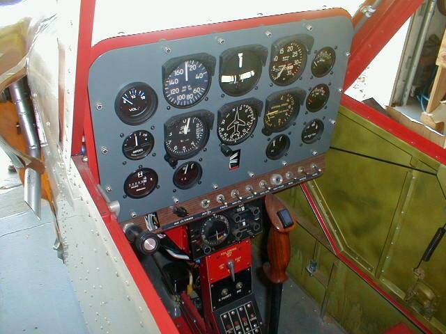
The wheels and brakes may be installed, and the airplane placed on the floor. Install fuel tank, instruments, seat and other items, such as brake handles and throttle, at your discretion. Install windshield. Make door as shown in General Assembly Drawing.
Rig your wings at a total of 2 degrees dihedral. Attach wings and install .020 fairings in the gap with sheet metal screws at your discretion. Attach and adjust ailerons. When you purchase your L680R engine, you will receive E-8 mounting plate and all hardware, etc. as per price sheet. Make and assemble the cowling. Then thoroughly inspect the aircraft for properly tightened bolts and free controls, and other airworthy items. We recommend that you have an aircraft mechanic check it over, as a disinterested observer, to assure your safety.
Weight and Balance Calculations
After completion of construction, it is a requirement of the FAA that you perform a weight and balance calculation, and have records of such in your paperwork for your plane. The following method should work well for you:
First, find a level place to weigh the airplane. Weigh in a no-wind condition. It is best to have three scales, if possible. Bathroom type scales are adequate, if you test them with known weights to see if they are accurate in the range needed. Place one scale under each main wheel (or one scale under one main wheel, with blocks under the other, to place the airplane in level position). Place another scale under the nose wheel, allowing the nose wheel to be the same distance off the ground as the main wheels.
Add the weights of the main wheel scales together (or double the reading of the single scale) to get the main wheel weight. Record this number. Record the number and weight at the nose wheel, also. This test should be performed with the fuel tank empty, and the cockpit empty. Add the figures together, and you will have the total empty weight of the airplane.
The Datum line is the leading edge of the wing. Use this point for all weight and balance calculations. Points forward of the Datum are negative (minus sign) and points aft of the Datum line are positive (plus). The main landing gear is 16.5 inches aft(+) of the Datum line and the nosewheel is 29.5 inches forward(-) of the Datum line.
Without fuel, the empty weight of your plane should be about 435 pounds (L680R version). Recommended gross weight is 750 pounds, not to be exceeded.
Calculations of the Center of Gravity (CG) should be made for pilots of 150, 170 and 220 pounds, with and without fuel and baggage. The CG range should be between 23% and 30% of the wing chord. 23% equals 9.7 inches aft of the Datum and 30% equals 12.6 inches aft of the Datum. Below is a sample calculation, based on our airplane. You must make your own calculations, putting in the weights you have found.
Sample Weight and Balance
Main Wheels: Weight: 381 lbs. Arm: +16.5in. Moment: +6286.5
Nose Wheel: Weight: 54 lbs. Arm: -29.5 in. Moment: -1593.0
Totals: Weight: 435 lbs. Moment: +4693.5
Notice that each moment is the weight multiplied by the arm. In order to find the arm for the complete machine, it is now necessary to divide the total of the moments (+4693.5) by the total weight (435). Thus:
+4693.5 / 435 = 10.78 inches, aft of Datum line.
To find the percent of chord location of the CG (for the empty airplane), divide this figure (+10.78) by the chord of the wing (42) Thus:
+10.78 / 42 = 25.4 % chord.
Our next step is to add the pilot, baggage and fuel. The arm for the fuel is minus, which means that its’ moment will be subtracted from the total moments. Pilot location is +14.625 from Datum, fuel is –9.875 from Datum, baggage is +36.875 from Datum. Thus:
ITEM WEIGHT ARM MOMENT
Airplane (empty) 435 lbs. +10.78 +4693.5
Pilot 170 lbs. +14.625 +2485.0
Fuel (6 lbs./gal.) 42 lbs. -9.875 -914.75
Baggage 20 lbs. +36.875 +737.5
——– ———– ————-
667 lbs. +7001.25
Again, divide the total of the moments by the total weight, giving an arm of +10.49, in this example. To find the percent of chord location of the CG (fully loaded), divide the arm by the chord. Thus: +10.49 / 42 = 25% Chord.
Make similar calculations for a 150 lb. pilot, full fuel, no baggage; and a 220 lb. pilot, no fuel, 30 lbs. baggage, and see if your airplane will remain within the CG range of 23% to 30% of Chord. Aerosport will calculate your Weight and Balance when you complete your airplane if you send us the weight figures.
Flight Manual
We find it very important to make several recommendations regarding test flight of the aircraft. Since hardly any of you are test pilots, these techniques have been developed with you in mind.
First, a few words about how the Quail flies. It is, as we have repeatedly emphasized, very easy to fly. But this does not mean that any pilot can climb right in and “go around the patch”. On the contrary, there are many things you must learn as you prepare for that first real flight.
Pre-Flight
When you assemble the airplane at the airport, it is the culmination of countless hours of work. Test flight is unfortunately the time that most errors are made. Be particularily cautious when your anxious friends try to help. Small errors that you may have made can cause major accidents if they are not caught. So, pace yourself slowly, and ignore taunts and suggestions that you immediately bore holes in the sky.
Before you attempt to start the engines, chock the airplane and be absolutely certain no tools or pieces or nuts or bolts are lying loose on the engines or airframe. Anything that can fly into the prop presents a very dangerous hazard to you and your spectators. Do not permit anyone to stand in the plane of the prop, in case of any loose object being tossed off the prop. Be positive that you have observed the correct fuel-oil mixture of 20:1 when you fuel the aircraft. (We recommend that you fuel the airplane from 5gallon cans. Use one quart of oil, snowmobile type, or Aeroshell non-detergent to 5 gallons premium auto gas, or 100 octane aviation gas.) Assume at all times that the switch is on, as the Aerosport engines have a magneto system. Put the choke on, crack the throttle some, and pull the engine through several times with the switch off. This should adequately get fuel through the carburetor. Then, observing all appropriate cautions, turn the switch on, and hit the electric starter. The engine should start immediately. Under normal conditions, after you first start, use the choke on, and switch on, until it fires.
The engines, in Aerosport’s experience, have proven to be the easiest starting aircraft powerplant we have seen.
Adjust your idle speed fairly high (1800-2000 rpm), so the engine will not shake excessively. As the break-in period is about twenty hours, the cylinder head temperature should be carefully monitored. The vibration level will decrease significantly with about three ours of operation. Consider 375 degrees F as a red line for the first few hours of operation. Later, your red line should be set 464 degrees F. Set the carburetors to peak rpm. Your two-cycle powerplant is dependant upon proper mixture for adequate lubrication. Hence, stay on the rich side of the mixture curve, remembering, though, that as you fly higher, the engine mixture will automatically become richer because of the thinner air. The L680R will reward you with years of trouble-free service if you observe these precautions.
Be absolutely certain that the airplane is securely tied and chocked when running up the engine, that no tools can be caught by the prop, and your body will reward you with many more years of trouble-free service!
Prior to each flight period, (at the run-up area of the runway), run up the engine until it is clear. Static rpm will be about 4100-4300 rpm with prop supplied.
The airplane should be continually monitored during the first hours of operation. Carefully inspect the hinges, rod ends, motor mounts, tank mounts, propeller, and all items for loosening, cracking, and friction before each flight. Be particularily careful about inspecting the wiring and fuel lines for abrasion and bad connections.
Taxi-Testing
The next phase of your flight-test program is slow taxi-testing. The Quail has a rudder bar, which may give you an initial tendency to over-control. You must learn to adjust to this tendency before progressing to high-speed ground runs. We recommend that you spend about an hour in slow taxiing. Most people rapidly adapt to the taxiing characteristics. Use this opportunity to wear in the brake shoes some. Remember that a dragging brake could overheat, and seize after take-off, leaving you with locked-up wheels. That, as you can imagine, is not a desirable situation!
High Speed Taxiing
Every pilot who has flown the Quail has been astonished by its ease of ground handling.
Gradually increase your power on each attempt until you are convinced that you can handle full throttle.
First Flight
After you finish phase three, knock off for a coke or coffee, and then thoroughly inspect your Quail again for any malfunctions or damage. Got up your nerve? Okay, fire her up and taxi out.
For your first take-offs, we suggest that you smoothly add all power as you accelerate down the runway. Then, at about 50 mph indicated, start a positive rotation to pick up the nose wheel. The airplane should immediately break ground, as soon as the nose rotates. Don’t rotate too soon! You should immediately relax back-pressure (do not pump the stick) and reduce power, so the airplane will settle back to the runway in the same attitude it had on take-off. We suggest that you repeat this technique while gradually climbing to higher altitudes above the runway.
Be very careful about flying down the runway with the airplane. If you were to hold full throttle, the airplane would very rapidly accelerate to almost 120mph in level flight. For this reason, back off on the throttle while flying up and down the runway. Please do not run out of runway with this kind of experimentation, it costs too much! You will find the excellent damping characteristics of the aluminum spring gear and the good brakes very impressive as you practice landings and take-offs.
First Flight Around the Field
Aerosport Recommends that you have at least five hours operation on your Quail engine before going around the field. In your preparation for this step, we encourage you to use the following check-list:
1) Clean spark plugs.
2) Fill with fuel (proper mixture!).
3) Check all wiring for abrasion marks. Be certain that all wires and fuel lines are tied down to either the engine or airframe in such a manner that they cannot be broken off by vibration.
4) Check coil brackets, motor mounts, prop hubs, and propellers for fatigue cracking and tightness.
5) Check throttle fittings for secure fasteners. Check carburetor throttle brackets for security on the shafts.
6) Check all cables and turnbuckles for proper safety wiring.
7) Inspect everything else not previously mentioned for proper airworthiness.
Once you are satisfied that the aircraft is ready, take a look at yourself. This flight will be pretty exciting, and will be thrill enough without the problems of gusty winds, high temperatures, and tired pilots. Pick a cool, calm morning or evening, and look ou for yourself, huh?
Okay, here goes. Fire up and head out to the active runway:
Check your seat-belt.
Helmet secure?
Perform your run-up.
When everything is okay, let her rip! Ease the nosewheel up and make your lift-off. Establish your climb at 65-70mph IAS. Climb straight ahead until you reach about 400 ft, while keeping an eye on the cylinder head temperature gauge. At about 400 ft., you should reduce power and drop the nose to a more comfortable attitude. It is entirely up to you now. Too exciting? Make a conventional pattern around the field, exactly as you have done in other airplanes. Then set up for a partial power approach to the numbers. We recommend that this be a fairly high speed approach at 65-70 indicated. Do not back off all the way off the throttle on approach, as the engines could load up and balk if you had to rapidly increase power. When you are several feet above the ground, level off, and fly along the runway a ways, until you can land a little short of your normal touch-down spot. This gives you an opportunity to re-orient yourself with a proper perspective. Otherwise you may have a tendency to fly into the ground, or try to land too high. Remember to hold a steady airspeed and continually monitor your speed.
Fortunately, the very effective stability and controllability of the airplane will permit you to grow rapidly secure.
Ready for more? Well, climb up to about 800 or 1000 feet and circle the field for about fifteen minutes, always being careful to maintain gliding distance to a runway. Make shallow turns and try to keep the engine at low cruise power of about 4000 rpm.
Remember that you may over control with the rudder bar until you get used to it. Whew, that’s enough for a while, isn’t it?
Make a thorough check-over of the airplane, particularly in the power plant area. Check each wire, cable and fuel line fitting. Satisfied? Start the next phase of testing.
Advanced Testing
This phase is as much a test of the pilot as it is of the aircraft. We recommend that you remain close to the airport for several hours of flying. You must learn to cruise the aircraft in a smooth range, until the engines have 200 hours time on them and are broken in. Continually monitor the cylinder head temperatures. You will rapidly note that in a low speed cruise condition on a cool morning or afternoon that temperatures will settle to below 350-370 degrees F. Often, we have cruised at about 290-310 degrees or less on cross-country flights after break-in. You should start experimenting with lower approach speeds and lower power settings on final approach. We recommend 55-60 IAS as a nice, comfortable approach speed. Experiment with rolling the airplane into S-turns until you are coordinated and can go from a 45 degree left wing down to a 45 degree right wing down series of S-turns. Grow familiar with the airplane!
Stalls are an avoidable maneuver, and we suggest that it is possible to fly for a lifetime without an accidental stall or spin. If you are the caliber of pilot that doesn’t need to stall or spin an airplane, you can be a very happy Quail pilot without ever performing these maneuvers. The FAA tendency today is to train private pilots to recognize he approach of a stall, and then avoid stalling.
If you are not of that bent, we recommend that you approach stalls as a progressive extension of slow flight without an extreme nose-high attitude. Maintain enough rpm on the engines to permit you to smoothly add power to recover flying speed. Do not attempt full power-on stalls without lots of practice, as the attitude is very high.
Any further aerobatic maneuvers are beyond the scope of this manual. We feel that the thrill of flying the Quail is enough for the average pilot, he needn’t spruce it up with stunts.
75 Hours? What to do?
It is a requirement of the FAA that you fly 75 hours in a restricted area before receiving permission to take extended trips. After several hours of loitering around the airport, you will probably be itching to show up at another field within your test area. It is amazing how confident you become as you leave the immediate airport area. There is something psychological about it, and you adjust rapidly to the idea. Before you go, be certain you have adequate fuel for the round trip! Also, completely check out the airplane.
Seventy-five hours is more than a year’s flying for the average pilot. Doubtless, you will become highly proficient at shooting landings and common maneuvers. The exceptional maneuverability of the airplane is going to prompt you to buzz and “shoot up” the hangar or a friend’s country home some time. This is illegal, and not recommended. When you do make that illegal buzz job, please be careful. Our reputation, your life, and the entire reputation of sport aviation is at stake. To us, your life is most important.