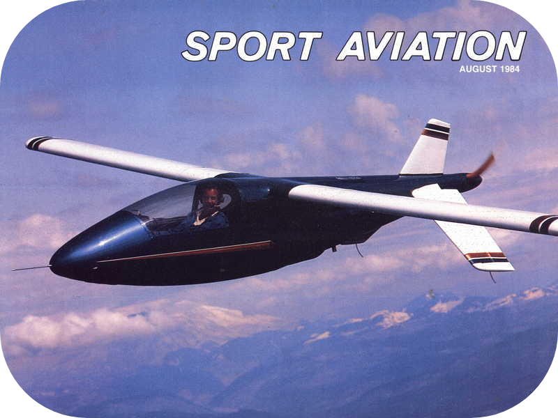


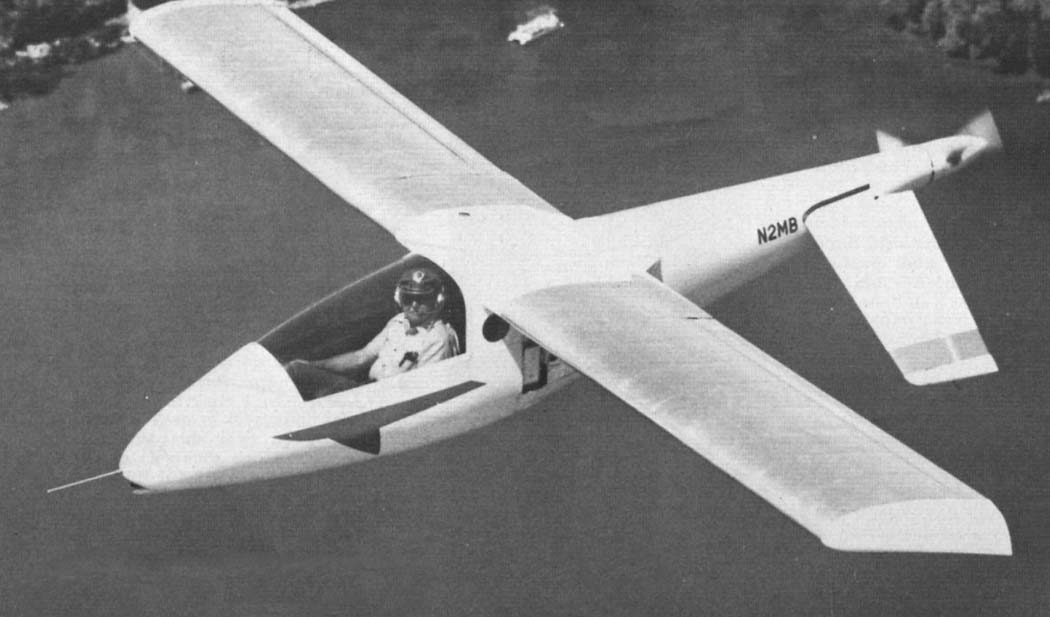
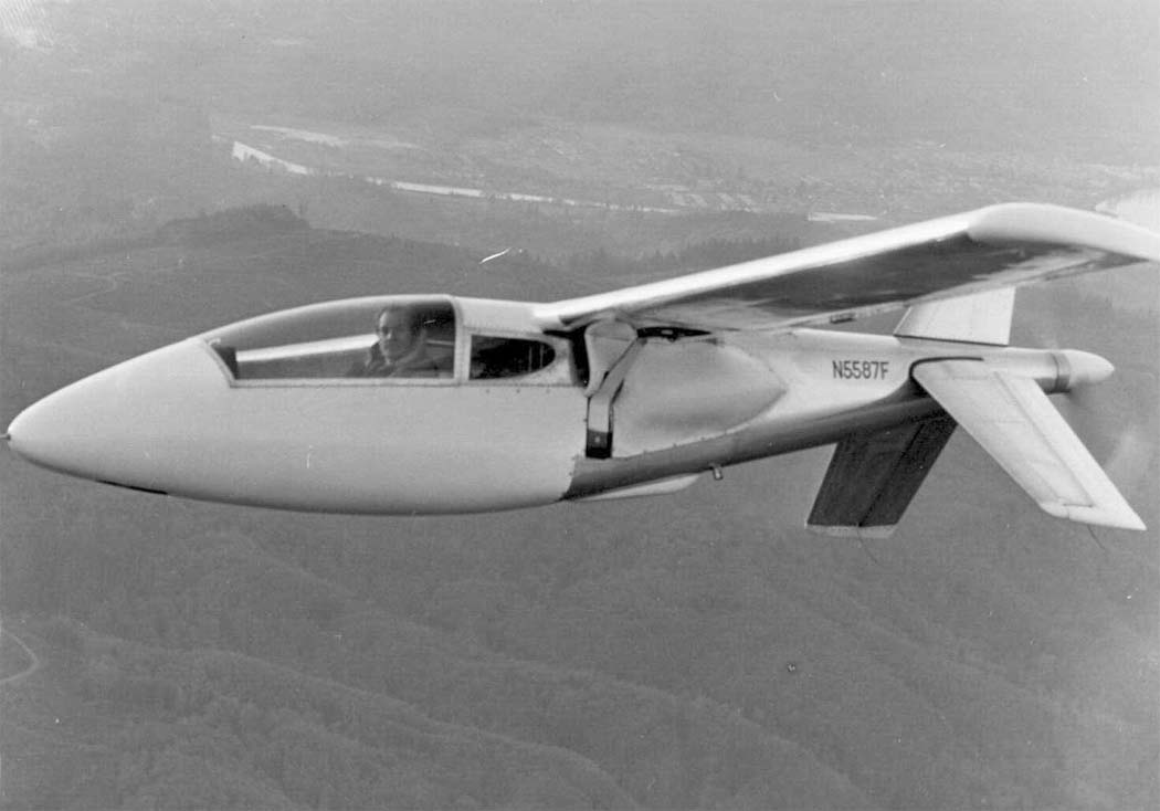
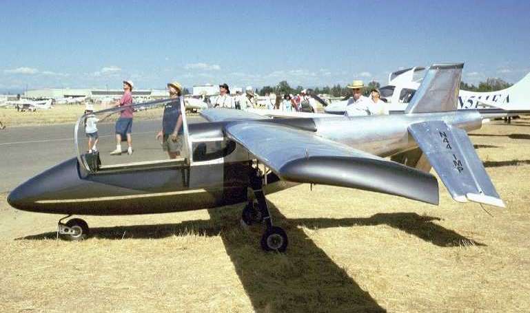
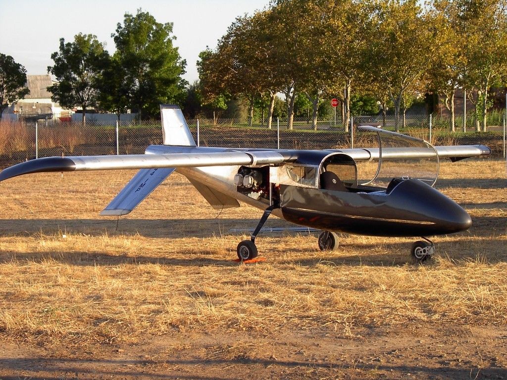
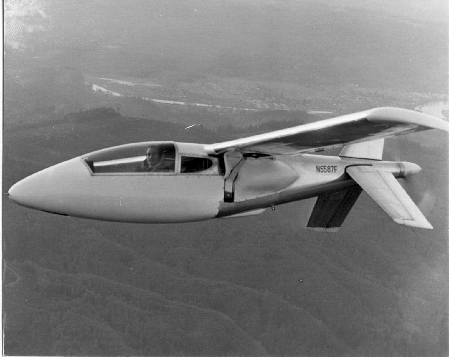
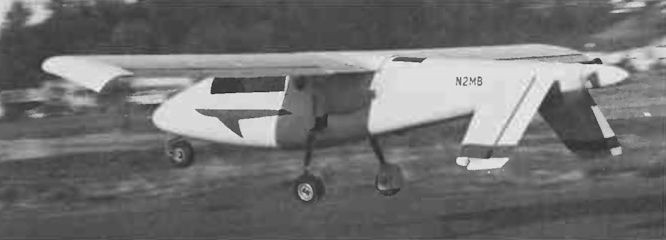
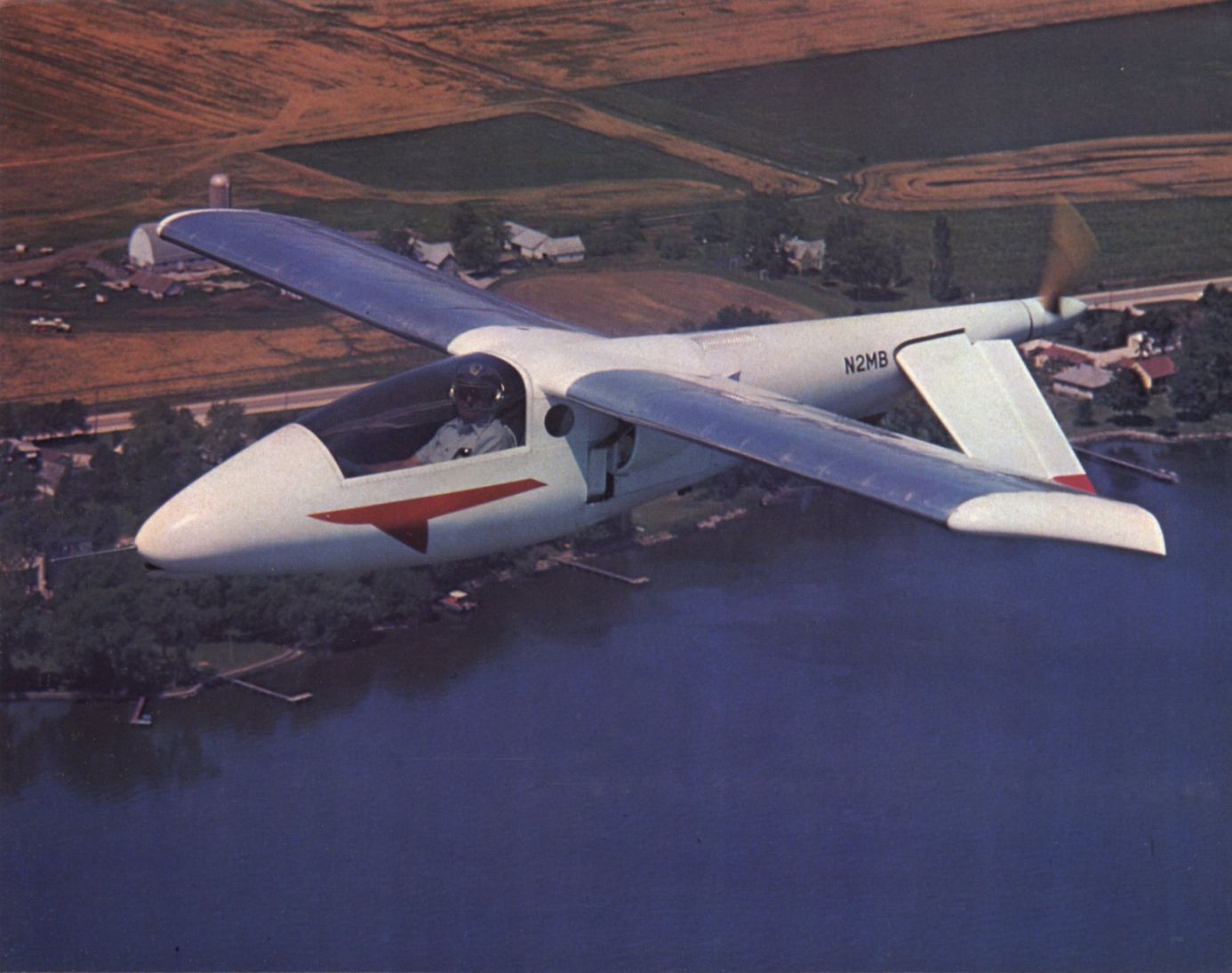
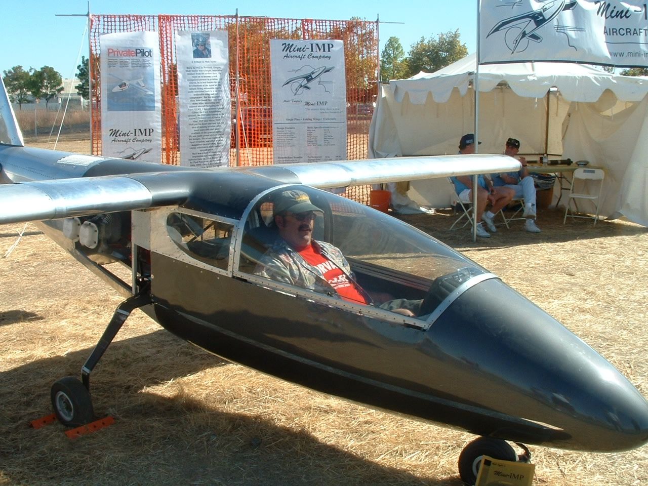
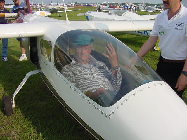
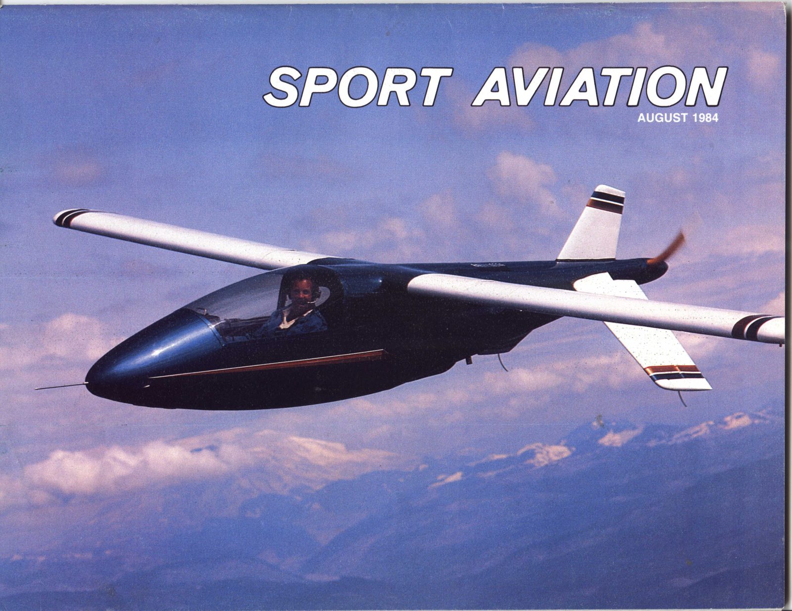


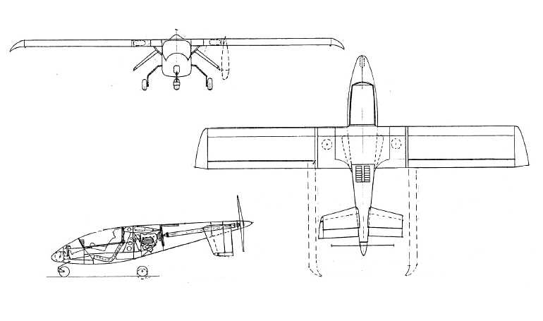
Aerocar Mini-IMP Moulton Taylor
The Mini-IMP is modern, sophisticated, high performance lightplane. It is extremely easy to fly, it has exceptional stability and maneuverability without being the least bit “touchy” or sensitive. It is extremely comfortable, has room enough and performance enough to carry heavy, big, or tall pilots. It has a very big baggage space in the O-200 powered model, and the VW engined version has a baggage space adequate for most short trips. The range possible with your version of the Mini-IMP is dependent on the tankage you incorporate in it when you build it. The drawings cover how to increase fuel capacity if you want it.
Do not expect the Mini-IMP (or any other design) to be all things. We do want to point out that the Mini-IMP is now a well proven configuration which does meet the design expectations which were laid down for it when it was originally conceived. At this time we feel that the Mini-IMP represents an optimum design for someone who wants an aircraft with its capabilities. It is an ideal “first project” for someone building his own aircraft. The design is as simple to build as any design with comparable performance.
Most potential builders are interested in “how long” it will take them to complete the construction of any homebuilt design they are contemplating. This is very difficult to answer since we have no way of knowing the degree of your skills, experience, equipment, facility, etc. It is impossible for anyone to give you an exact estimate of how long it will take you to put a Mini-IMP together. It depends entirely on how fast you work, how long you take to talk things over with the multitude of friends that are bound to drop in to see your project, and how long it takes you to get all of the parts and materials together. If you are handy with tools and you have good facilities and working space, you should be able to build your Mini-Imp in approximately 1500-2000 hours. If you are not handy with tools, find difficulty in reading drawings, and find it impossible to follow instructions, it will take you longer. This compares with an estimated 10,000 hours to build a Falco or 1,500 hours to assemble the kit of a typical fixed-wing, fixed-gear aircraft. The longest documented amount of time taken was 5000 hours by Seńor Bernardo de Sousa Dantas of Sao Paulo, Brazil. He made many changes and also performed his own conversion on the plentiful VW engine. You will probably take much less time. When people quote so many years to build an aircraft, they mean that they chose to spread the number of hours required over that many years, for whatever reason.
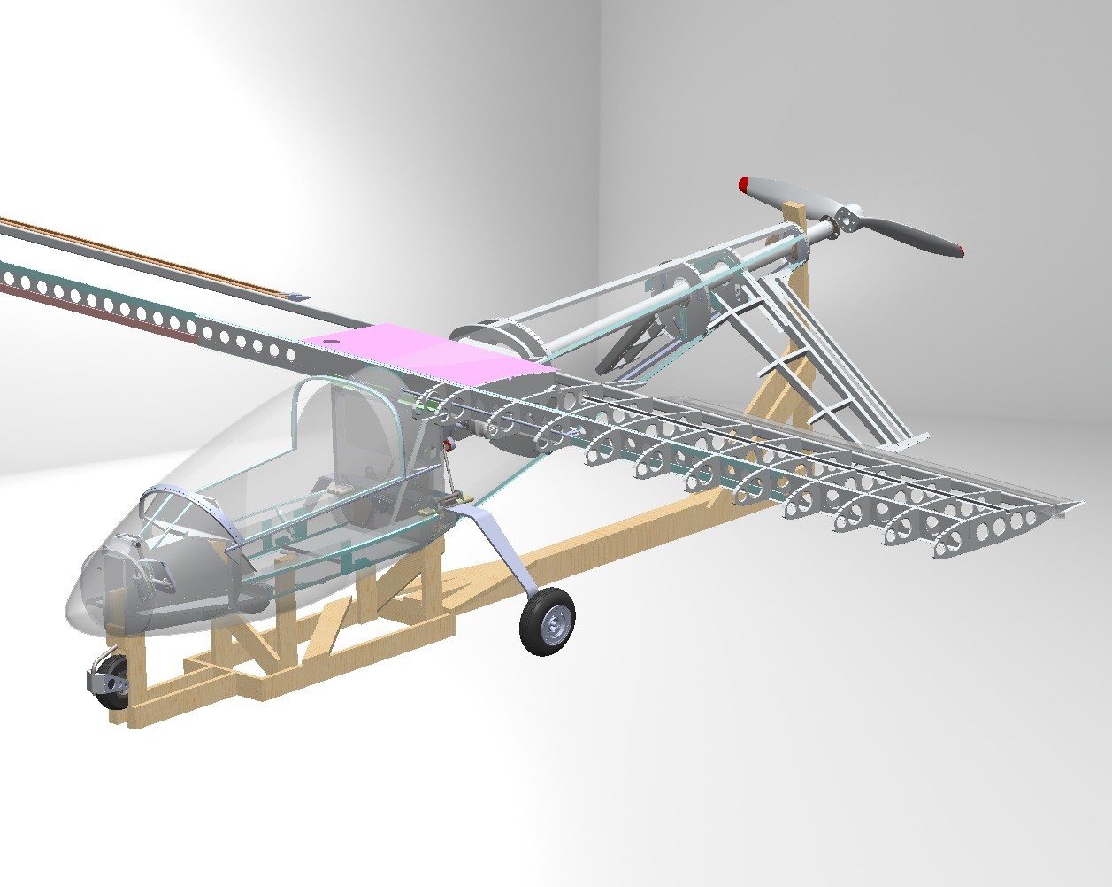
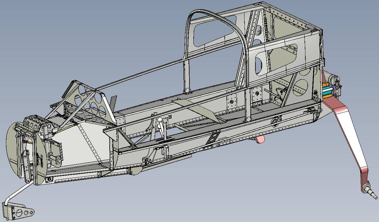
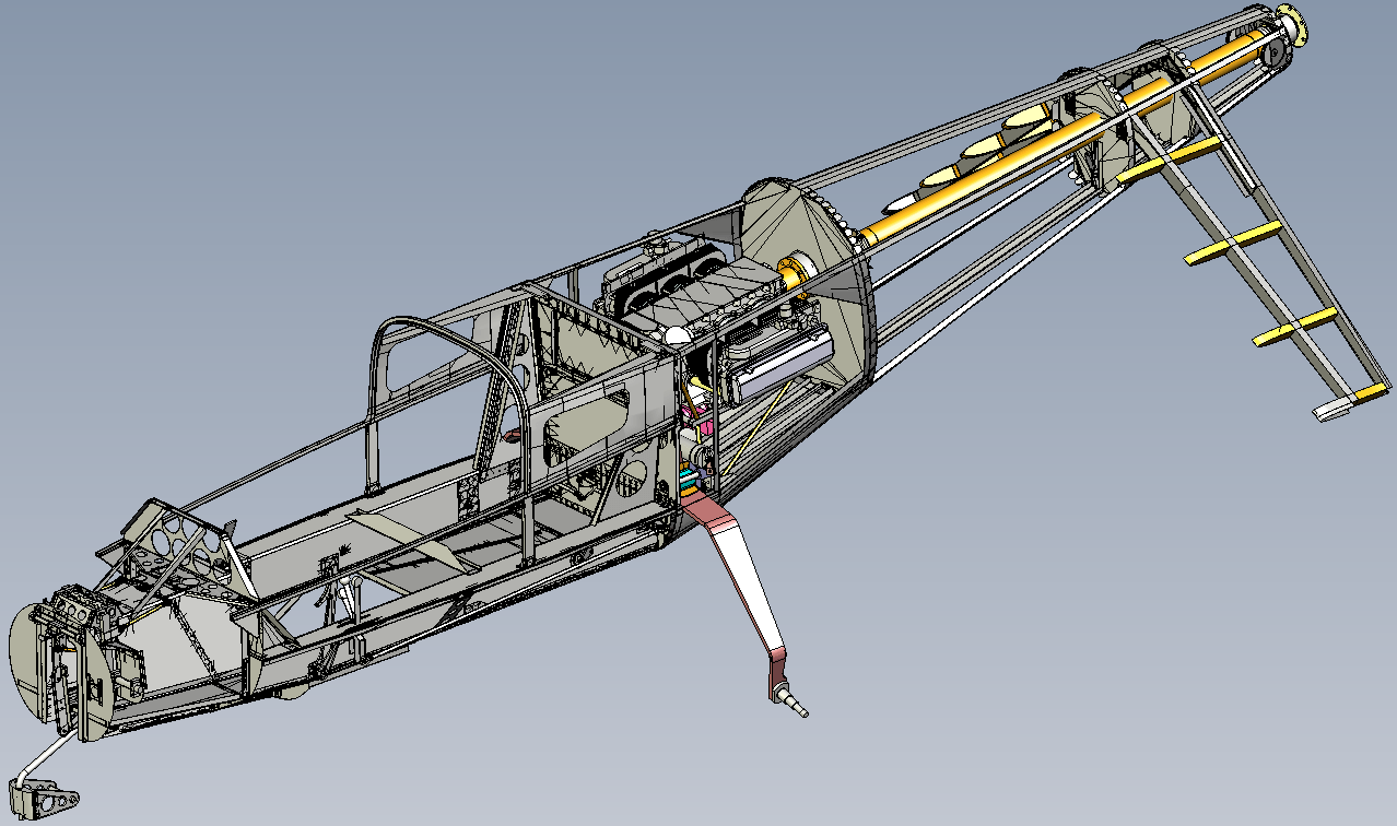
The years of experience that the designer of the Mini-IMP acquired with homebuilders have shown that the ideal homebuilt design should require no welding. It should require a minimum of tools, and it should not require many costly machined parts. While it is impossible to design an aircraft with out some of this complication, the Mini-IMP has been designed to keep these requirements to a bare minimum.
The Mini-IMP has been designed to be built with a bare minimum of special tools. Thus, a drill press with variable speed, a metal-cutting band saw with variable speed, and a bench sanding belt are the only power tools necessary other than usual hand tools. A variable speed 3/8” chuck electric hand drill (or equivalent) is necessary. A propane torch for brass brazing is desirable, although this work can be easily done by some job shop. A variety of high speed drills are needed, and these are listed in the drawings. Good quality sheet metal snips are required. A hand riveter is required, and if the aircraft is to be flush riveted, a hand dimpling adapter for the riveter is needed. There are a few long sheet metal members that must be sheared. These can be done by a job shop, or can be hand done and the edges reworked and filed to get the desired smooth edges. There are some members which must be bent, but these can be bent over the edge of suitable planks. Drawings on how to do this are included in the drawing set. Other than these special considerations, the builder needs a good work bench, a heavy vice, and the usual hand tools found in any hardware store. The Mini-IMP can be built in a single car garage. Wooden jigs to support the structure during construction can be made from 1 X 4 or 2 X 4 material available at any lumber yard. The drawing set lists all tools and hardware needed for construction. Outside contractors are being lined up to supply many of the hard to build assemblies. Although none of these are really complicated or expensive, it is recognized that some builders would rather buy as much as possible and still stay legal within the FAA requirement that they do 51% of the work. This requirement is easily met when building the Mini-IMP since there just isn’t too much that is needed other than putting it together. The basic structural material for the Mini-IMP is 2024-T3 aluminum sheet. There is no heat treating of the aluminum required. The only heat treated parts in the aircraft are the main landing gear legs and the nosewheel leg. These components are available.
Although there is some fiberglass component trimming necessary in the construction of the Mini-IMP there is absolutely no fiberglass lay-up or fabrication necessary, with none of the fumes, mess, and other problems such as skin allergies (necessitating work gloves, etc.).
Specifications Aerocar Mini-IMP Moulton Taylor:
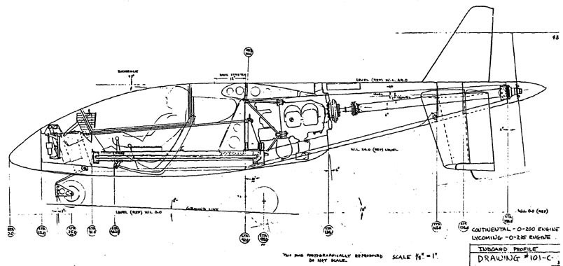
- Engine: Continental O-200, 100 hp
- Hp range: 80-125
- Speed max: 200 mph
- Cruise: 170 mph
- Range: 500 sm
- Stall: 45 mph
- ROC: 1500 fpm
- Take-off dist: 600 ft
- Landing dist: 600 ft
- Service ceiling: 20,000 ft
- Fuel cap: 13 USG
- Weight empty: 700 lb
- Gross: 1000 lb
- Height: 4 ft
- Length: 16 ft
- Wing span: 27 ft
- Seats: 1
- Cockpit with: 26 in
- Landing gear: retractable nose wheel
- Engine: 60-hp
- Gross Wt. 800 lbs
- Empty Wt. 500 lbs
- Fuel capacity 12+ USG
- Wingspan 25’
- Length 16’
- Cruise 150+ mph
- Stall 48 mph
- Climb rate 1200 fpm
- Takeoff run 800 ft
- Range 500 sm